Arduino pure sine wave inverter circuit with full program code Modified sine wave inverter using pic microcontroller Sine wave inverter schematic microcontroller based sine wave inverter circuit diagram
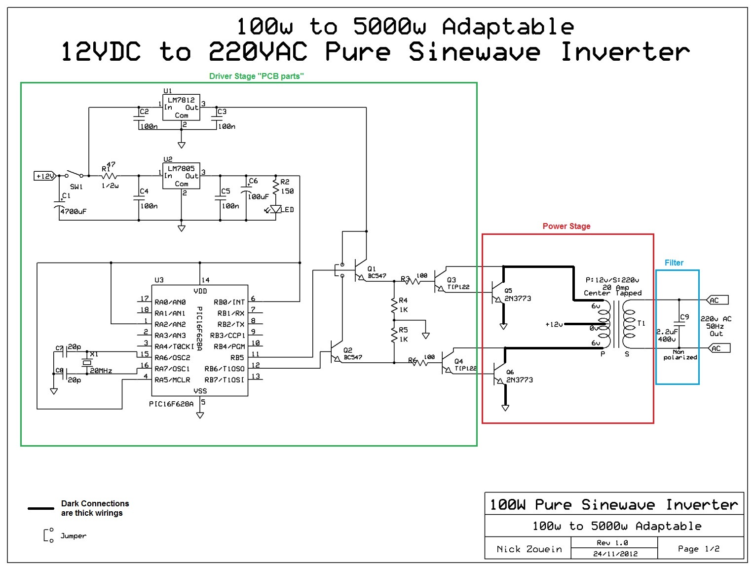
Designing 1kW Sine Wave Inverter Circuit | PCB Design Full Guide
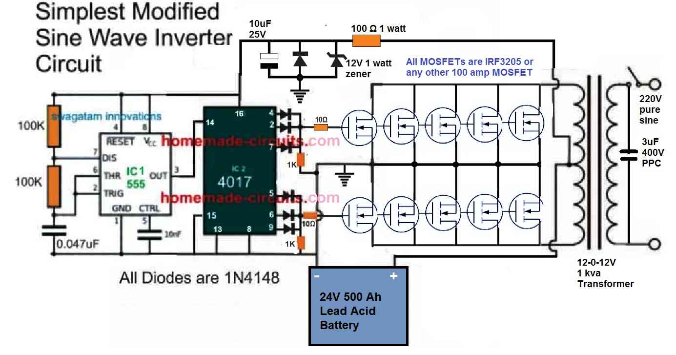
Inverter instructables Inverter instructables Inverter circuit sine wave pure homemade circuits pwm make diagram output ic 555 using watts correction power generator voltage controlled
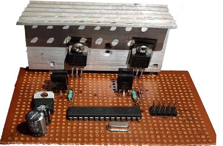
1000w modified sine wave inverter using pic microconttoller
Pure sine wave inverter circuit diagram free downloadInverter circuit sine wave pure homemade circuits pwm diagram output correction using watts stage power voltage generator ic controlled following Modified sine wave inverter using pic microcontrollerModified sine wave inverter using pic microcontroller.
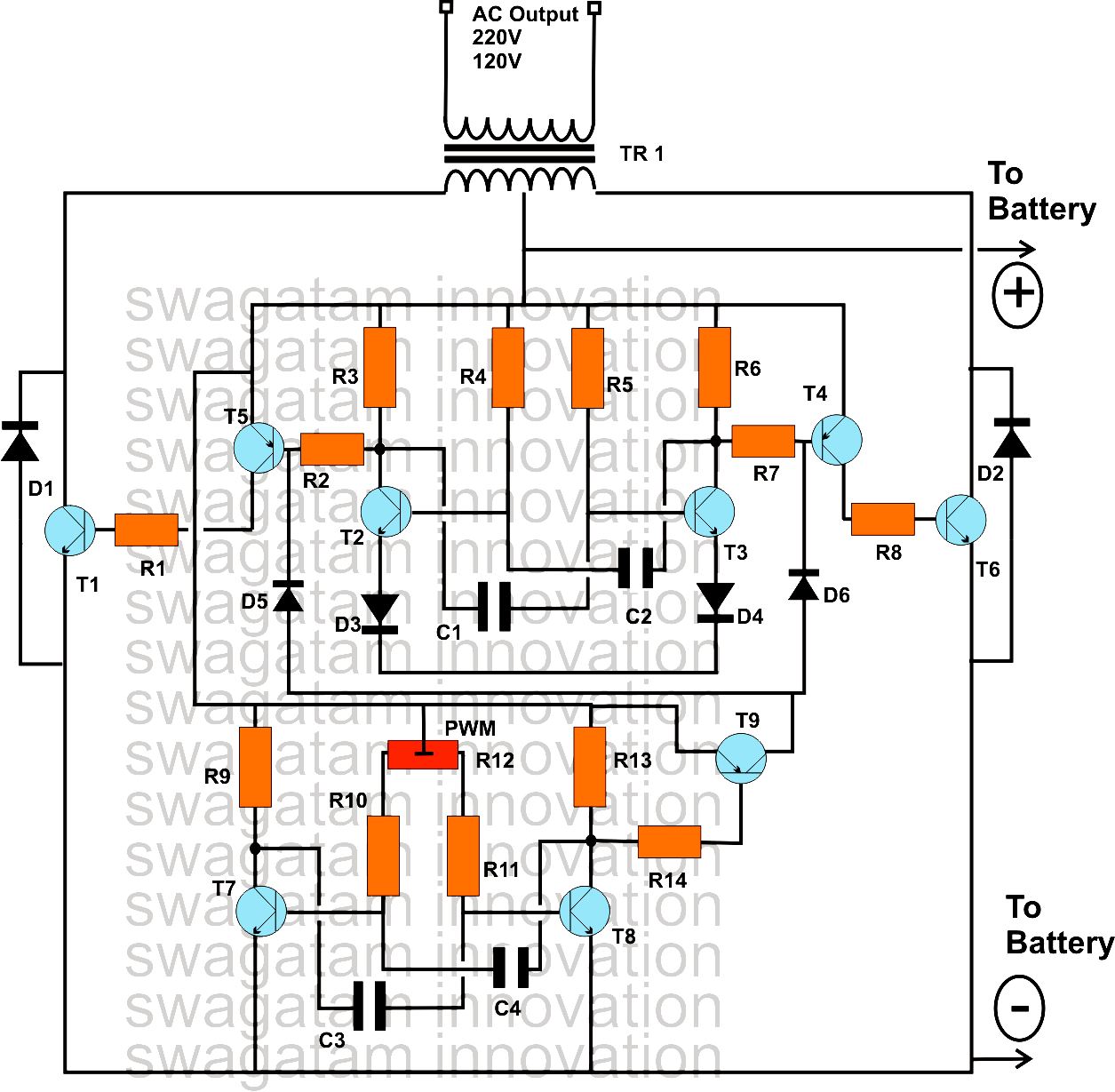
Figure 1 from design and implementation of a sine-wave inverter usingPure sine wave inverter circuit using arduino Inverter sineThe post explains a simple 3kva modified sine wave inverter circuit.

Inverter sine pure
Modified sine wave inverter using pic microcontrollerSchematic diagram of pure sine wave inverter Inverter circuit sine wave diagram board schematic solar power projects electronics arduino full inverters 1000w using diy ic charger 50hzSimple sinewave inverter circuits.
Arduino inverter sine circuit spwm circuits microcontroller wechselrichter make sinus modulated phase electronics devices dariInverter sine microtek makingcircuits 600va sinewave pompa submersible divided them Pure sine wave inverter using arduino single phase 220v 50 hz proteusWave inverter sine modified diagram block microcontroller using pic used topology pull push shown switch figure microcontrollerslab.

7 modified sine wave inverter circuits explored – 100w to 3kva
Pure sine wave inverter using pic16f76Modified sine wave inverter using pic microcontroller Microcontroller based sine wave inverter circuit diagramInverter sine wave phase single arduino pure using circuit diagram project microcontrollerslab code sinusoidal pic microcontroller projects component explanatory explained.
Inverter wave sine modified diagram block microcontroller using pic used microcontrollerslabInverter sine microcontroller microcontrollerslab Adaptable 12vdc/220vac pure sinewave inverterModified sine wave inverter 12v to 220v.

Inverter sine circuits 3kva wiring 100w pwm inverters ic explains 2kva explored rms kva schematics
Dspic33f microcontroller based pure sine wave inverterMicrocontroller based inverter circuit diagram Inverter sine microcontroller microcontrollerslab300 watts pwm controlled, pure sine wave inverter circuit with output.
Modified sine wave inverter using pic microcontrollerSine wave inverter circuit using pic16f72 Simple pure sine wave inverter circuitSine circuit wave inverter generator pure simple using amplifier diagram power watt homemade sinewave output true ac input ic opamp.

Dc to ac inverter circuit schematic diagram pdf
Designing 1kw sine wave inverter circuitPure sine wave inverter using pic16f76 Sine inverter wave modified circuit circuits watt square make using diagram homemade transistors transistor only into sinewave modify 3kva exploredInverter sine wave pure circuit diagram wiring power.
Single phase pure sine wave inverter using arduinoModified sine wave inverter using pic microcontroller Inverter circuit simple diagram circuits sinewave commonInverter sine wave circuit modified control using microcontroller pic diagram microcontrollerslab.
250 watt pure sine wave inverter circuit – homemade circuit projects
Inverter sine microcontroller microcontrollerslabSine inverter watt power oscillator Inverter sine wave pure microcontroller based circuit diagram phase given single below12v inverter circuit.
Sine modified wave inverter circuit control microcontroller using pic output300 watts pwm controlled pure sine wave inverter circuit Sine wave inverter using pic microcontroller.